Lunabotics Rover - Senior Design
Teleoperable Mining Rover (2024)
I want to first and foremost say that this project was a TEAM EFFORT. This project was a result of the blood, sweat, and tears of a whole team of people. I’m extremely thankful for the opportunity I had to work on this project, I learned so much about project management, team management, mechanical design, design for manufacturing, and more. I’d wager I learned more from this project than the rest of my degree combined.
Overview
With the caveat out of the way, what was this project? The goal of this project was to develop a robotic system to collect, transport, and deposit lunar regolith to build berms. In an actual mission scenario, these berms could be used to catch debris produced during rocket launches from the lunar surface and protect habitats and other lunar installations.
This was my third year on the Lunabotics team, and had become the club president. With me were my two comrades from the previous year, Nick and Cheyenne. The three of us were the administrative team, handling fundraising, communication with the university, and other administrative things in addition to our design and fabrication duties.
Additionally to this, I was designated Hopper Team Lead, working with another team member to design a superstructure that would collect and deposit the regolith. I took it upon myself to design the deposition mechanism, which I referred to as the “Deposition Plate” or “Hopper Deposition” mechanism. I'll do a deep dive on this later in the article.
Criteria for Success
Being that this was a project done for a grade, we needed some objective criteria to know if the project was successful. This was codified in our criteria for success. These were a list of goals that every decision would be made based on.
- Robot will maintain mobility when two or fewer wheels are in contact with lunar simulant surface
- Robot will capture encoder data from drivetrain
- Robot will have a minimum onboard power capacity to operate continuously for 35 minutes
- Robot will weigh less than 60kg
- Robot will fit within a volume of 1.45 x 0.7 x 0.7 meters
- Robot will mine, transport, and deliver a minimum of 0.1 cubic meters of lunar simulant
These criteria (along with the unwritten criteria to finish on time and under budget) drove all design decisions.
The Deposition Plate
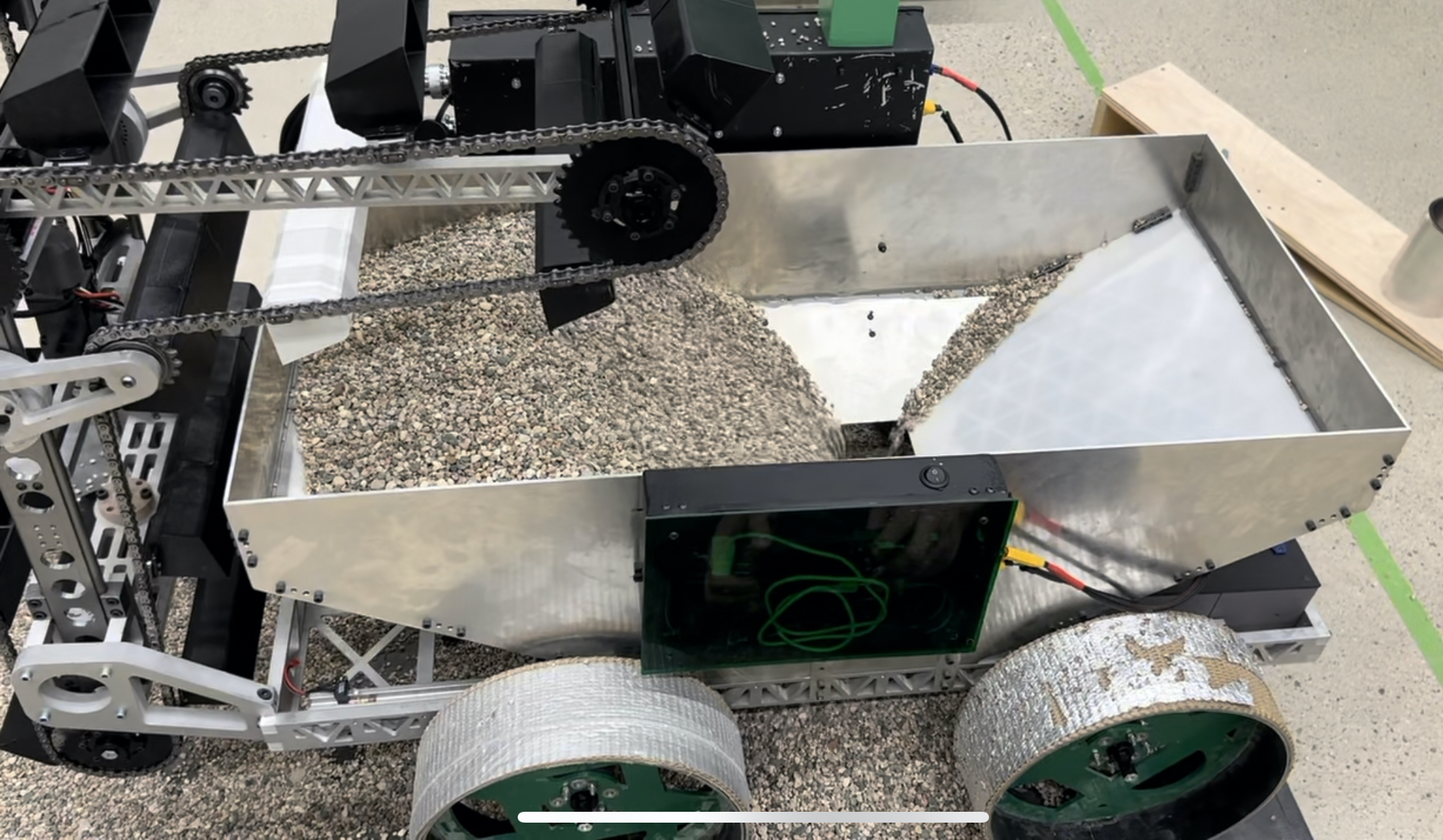
My primary mechanical focus was on the Hopper Deposition mechanism, which was responsible for releasing collected material into the designated area. While a number of deposition mechanisms were considered, a “belly dump” system was chosen, where the bottom surface of the hopper would slide out to release the regolith. While this mechanism was relatively simple to design, I spent hundreds of hours refining this mechanism to ensure that not only would it work perfectly, but it would also be as light as possible.

The backbone of my strategy to move the plate was a lead screw and linear carriage system. IGUS had graciously offered to sponsor our team for the year, and they donated a significant portion of our linear motion supplies, in addition to providing a direct line of communication to ask any implementation questions.
Lead screw
The specific lead screw I chose was an PTGSG20X401RAL, which is a lot of text to describe a 20mm diameter aluminum lead screw with 4mm thread pitch. This was coupled with a JSRM-TR134 nut, which is circular with two flats to prevent rotation. These were selected by using a standard lead screw calculation, and verified with IGUS’ online calculators (results were within a rounding error)
The lead screw would be driven by a REV Robotics Neo550 Brushless motor running through a VEX Versaplanetary gearbox. The gearbox was specced to 35:1 ratio with a ½" round output shaft. To join this gearbox to the lead screw, a Misumi shaft coupler was used, which was the only one I could find that would adapt ½" to 20mm.
Linear Rails
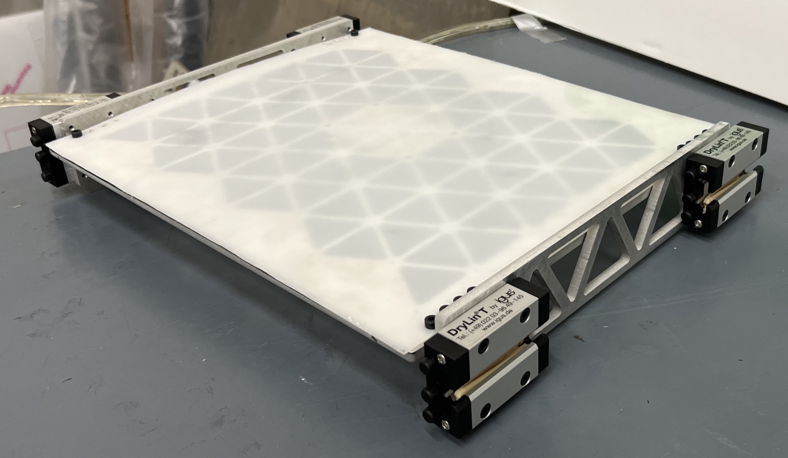
To keep everything on the rails (heh), Linear carriages were used, also from IGUS. While the team in the past had used their W-series (flat bar with circular shapes on each end) for the mining mechanism, I decided to use the T profile in my application (20mm set I believe). This turned out to be an extremely good choice due to the carriages having features built in to adjust the tolerance. This meant that the distance between the carriages could be adjusted without requiring much, or any hassle. Comparatively, the mining mechanism, which was still using the W profile, needed to be fiddled with extensively to get the mechanism to move smoothly. I will be recommending that the team use this system in the future to minimize any custom work needed to add this adjustment. The linear rails would mount to the sides of chassis, and would span the whole length of the bot. In hindsight, these could have been shortened, but I’m glad I left them in case I needed to move the motor to the other end for some reason.
Structure
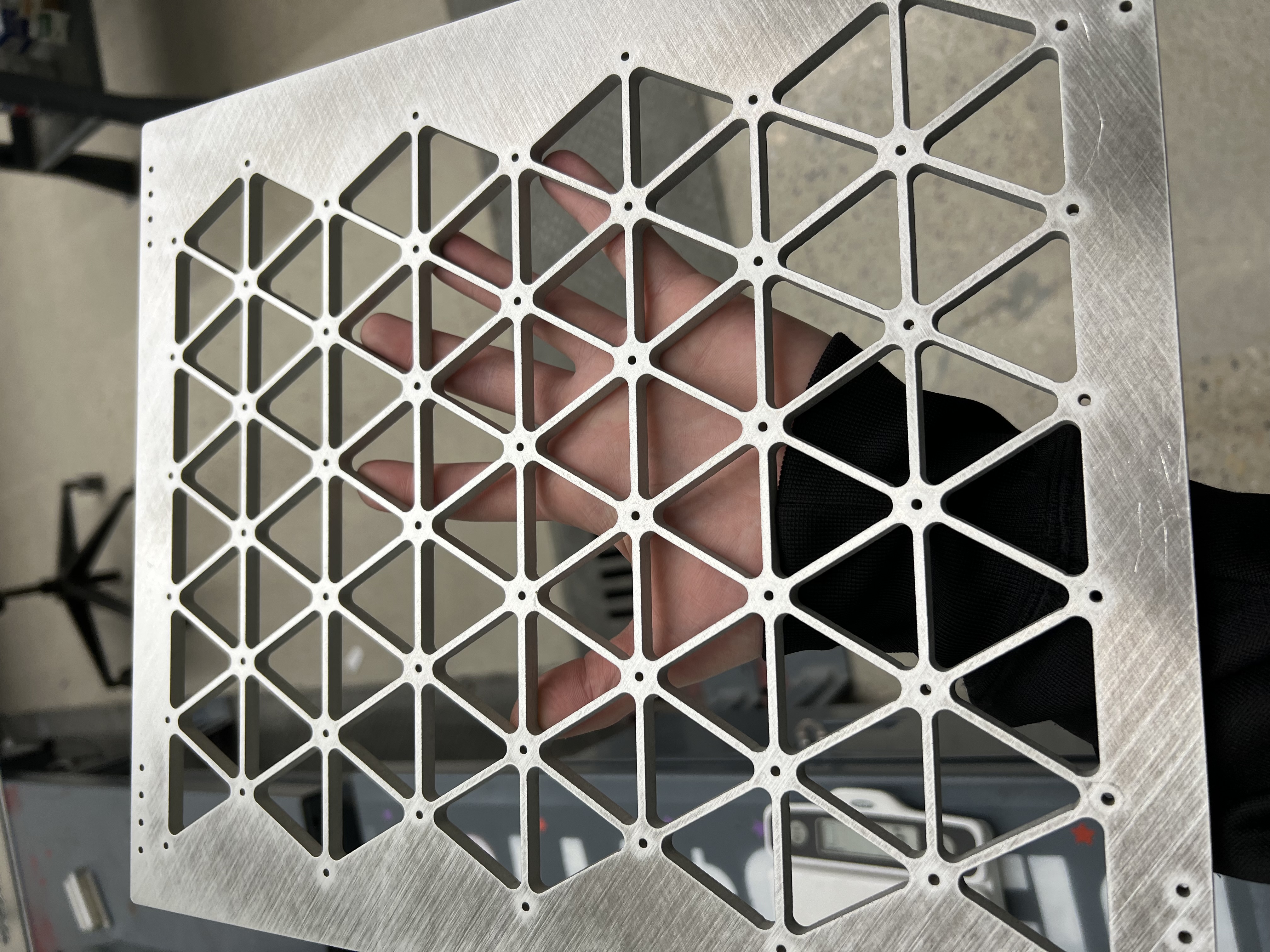
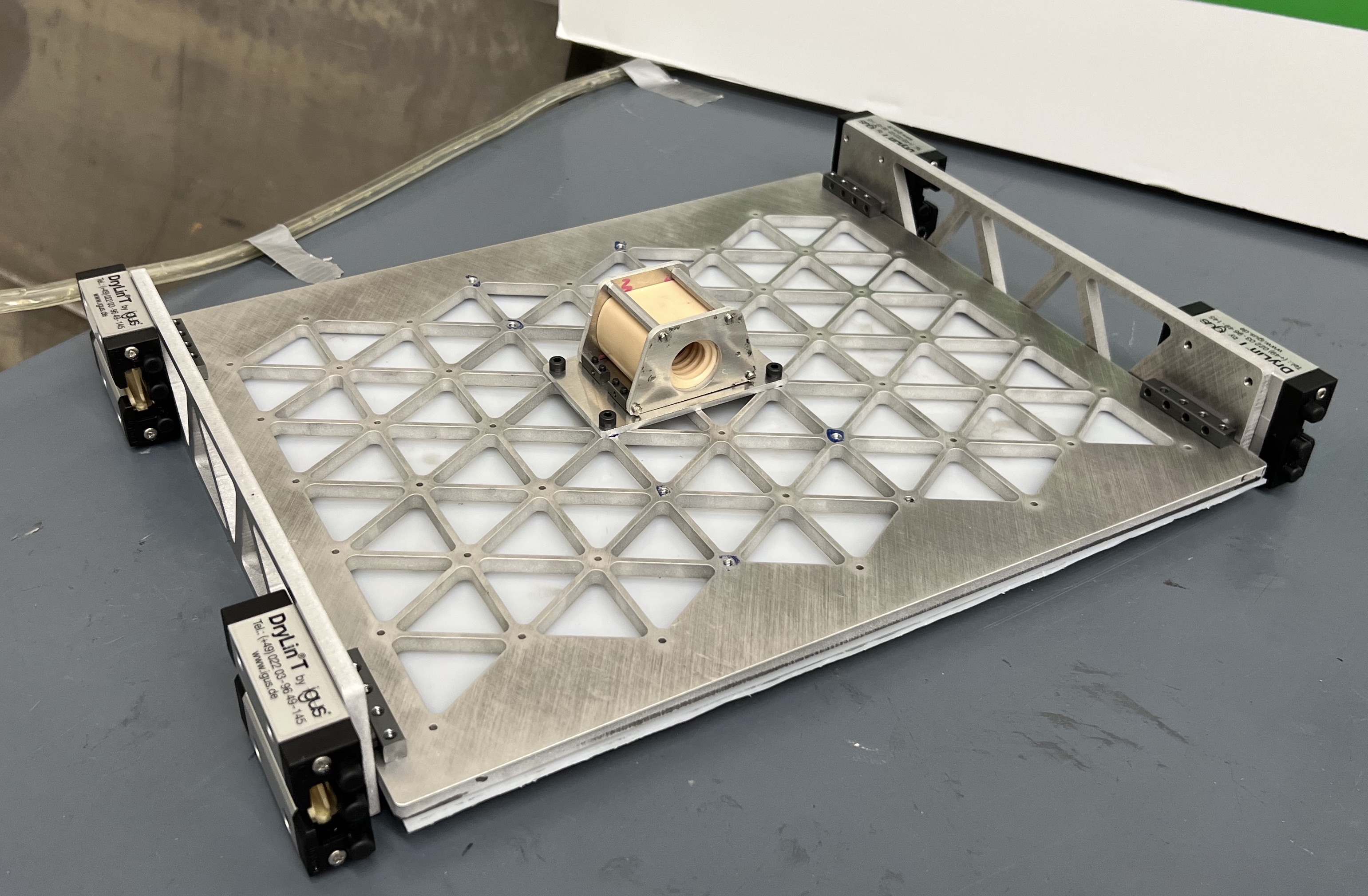
The structure was made up of water jet components made by another of our gracious sponsors, PS Industries. The strucure was designed such that it could be assembled in three small subassemblies which were then combined. Two of the subassemblies are identical, each comprised of two carriages bolted to a water jet plate. These are the “side pods.” The plate attaching the pods has a truss geometry water jet into it to reduce weight. The "Plate” subassembly is comprised of a flat plastic plate on top of a ¼" thick aluminum plate with an isogrid structure cut into it.

An isogrid structure is functionally a 2D truss structure that can be applied to a plate rather than a beam to reduce weight while maintaining stiffness. Traditional isogrids are made by pocketing a sheet of material (the holes don’t go all the way through), though this can cost an exorbitant amount of money (Protolabs quoted $1400 for this part due to the size and required machine time).
Through talking with Nick (and John, our graduate advisor and my roomate at an internship we did together), we devised a strategy to cut this cost to a fraction of the Protolabs order. This fraction was 1/34, perhaps 7/237. The strategy was to bond the isogrid. To do this, you would cut two plates: one thick with the isogrid pattern, and another really thin that just had the mounting holes. You would sandwich these two plates together and bond them together with some sort of glue or epoxy.
While this was a nifty strategy, we ended up skipping the bonding process. This was due to load testing showing the unbonded mechanism could withstand the whole 300lb load without measurable deflection. This let us keep the plate modular in case we needed to change something later down the line and remove a whole (risky!) manufacturing step.
For more info on isogrids: https://femci.gsfc.nasa.gov/isogrid/NASA-CR-124075_Isogrid_Design.pdf
The fourth subassembly is the nut mount, which holds the Leadscrew Nut. This is made up of several waterjet plates that attach to each other and form a small cage around the nut. This bolts into a set of 4 tapped holes on the bottom of the isogrid plate.
One of the techniques that the deposition plate uses to reduce manufacturing steps is Nutstrip. These are small aluminum blocks with holes tapped at regular intervals at right angles to each other. This allowed me to eliminate a significant amount of tapping in the fabrication process. The specific nutstrip selected was from Fingertech Robotics, as they offered the largest selection of sizes. The Nut mount uses four pieces of M3 “Corner” nutstrip to attach plates, while the side pods are attached to the isogrid plate using four M4 nutstrips.
This mechanism went together smoothly, and installed smoothly, and moved smoothly. Even when 300lb of sand was placed over it, it still managed to move extremely easily.


Things that went well:
Nutstrip is awesome and should be used way more frequently. In the future, I’m going to push the team to use as much nutstrip as possible to reduce the amount of tapping necessary, and to move holes from the sides of waterjet parts (where kerf mandates a secondary machining operation to square up the sides) to the faces (which don’t require as much machining).
Building adjustments into linear motion mechanisms is a good idea. I used the inbuilt tolerance adjustment in the carriages, but also added a bunch of tolerance to the width because I was worried about the chassis rails being too close together and not having enough space for the mechanism to slide freely. While adding tolerance in both areas fely like overkill, due to a number of manufacturing issues cropping up, I am extremely glad I did.
Things I wish I had done differently:
Support other end of lead screw. It wobbled more than I would like. Nick had mentioned this during the rush to finish the bot, but I wanted to focus on our main criteria instead. While the wobble was extremely noticeable, it did not impede performance.
I could have cut maybe another pound out of the mechanism, especially if I had allowed more deflection. A thinner plate for the isogrid, more material pulled out of the side trusses, lighter fasteners, there were a number of options.
This was only one small portion of the overall system, but one that I poured a ton of time into trying to make perfect, and I think I got pretty close.